edge trigger circuit
VLSI SoC Design: Dual-Edge Triggered Flip Flop. 9 Pictures about VLSI SoC Design: Dual-Edge Triggered Flip Flop : Flip Flop Triggering-HIGH,LOW,POSITIVE,and NEGATIVE Edge Triggering, The Integrated-Circuit D Latch (7475) and also Clock divider by 3.
VLSI SoC Design: Dual-Edge Triggered Flip Flop
 vlsi-soc.blogspot.com
triggered vlsi
Electronics Club - 555 Bistable
 electronicsclub.info
555 bistable circuit timer multivibrator circuits ic inputs monostable electronicsclub info
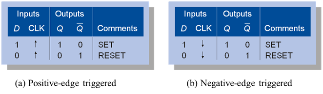
The Integrated-Circuit D Latch (7475)
 grace.bluegrass.kctcs.edu
flip flop circuit truth table edge triggered negative 7475 latch arrow integrated bluegrass flops kctcs grace edu
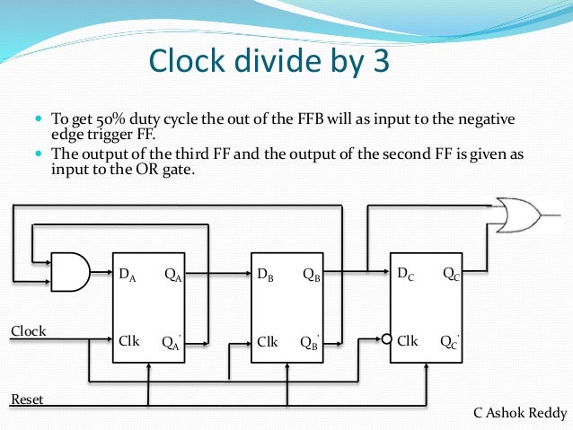
Clock Divider By 3
 www.slideshare.net
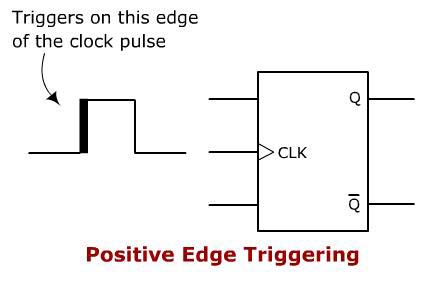
Flip Flop Triggering-HIGH,LOW,POSITIVE,and NEGATIVE Edge Triggering
 www.circuitstoday.com
triggering edge positive flip flop flops negative circuitstoday
555 Timer IC Pin Diagram Features And Applications | 555 Timer Working
 www.circuitspedia.com
555 timer astable mode ic diagram circuit multivibrator monostable application
 venturebeat.com
14827 Unit 4_clocked_flip_flops
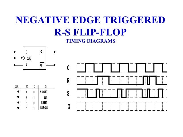 www.slideshare.net
triggered timing clocked clk
Arduino Toggle Push Power On Off Latch Switch
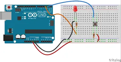 mechatrofice.com
input
Flip flop circuit truth table edge triggered negative 7475 latch arrow integrated bluegrass flops kctcs grace edu. 555 timer ic pin diagram features and applications. Electronics club